
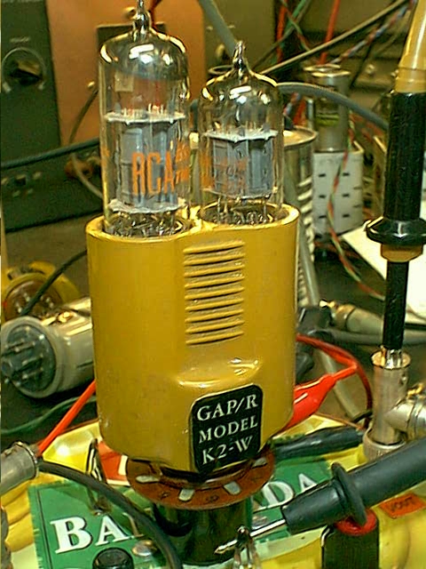
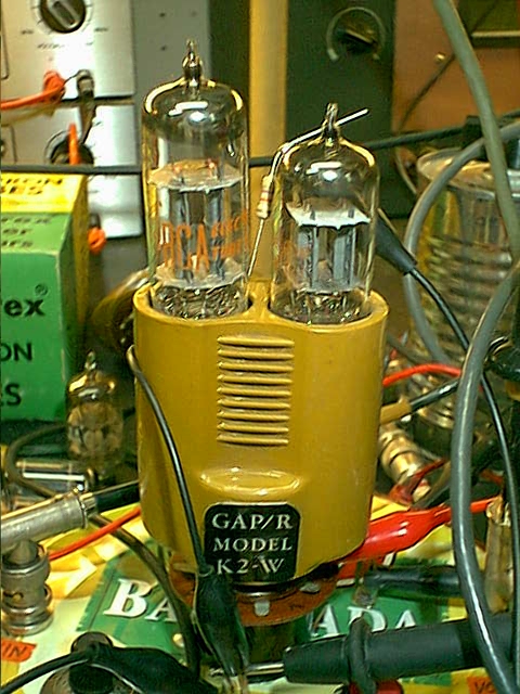
This page shows the effect of substituting the two 12AX7 tubes in the K2-W with other tubes.
Check the schematic diagram for the K2-W.
Data sheets for 12AX7 12BZ7 12AZ7 12AV7.
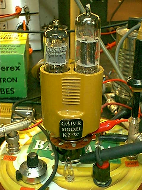
The original configuration with 12AX7 at V1 and V2.

The 12BZ7, which is a larger version of the 12AX7, with the same intrinsic voltage gain (mu) of 100 but twice the transconductance at 2.5mS and 50% higher plate dissipation at 1.5W. The 12BZ7 appears to affect K2-W performance slightly, improving the open loop gain of the K2-W from 15k to 30k. I attribute this to the lower internal impedance of the 12BZ7. This lower impedance is better able to drive the internal load resistors of the K2-W. In order to get the doubling in gain I reduced positive feedback from the output to the second stage with 47kOhms from pin8 of V2 to ground. The 12BZ7 benefit is visible in the graphs below as a reduction in curvature of the transfer function. Voltage swing was essentially unaffected.
Another possible benefit that I did not verify with measurement is the reduction in output resistance. The 12AX7 has about 500 Ohms of output resistance as a cathode follower. The 12BZ7 is slightly lower with 400 Ohms at the same 2.5mA unloaded quiescent current. But you can load it much more heavily than the 12AX7, with a substantial reduction in output resistance. The 12AX7 in the cathode follower section of the K2-W is already running close to it's rated limits. The 12BZ7 has room to spare. If you are going to run the 12BZ7 as the output tube heavily loaded, you may not need to tweak back the internal positive feedback at pin 8 of V2. For example, a 2k load would attenuate the open loop output resistance by 20%, which is equivalent to adding the 47k shunt at V2 Pin 8. At this heavy load, you also loose a lot of output swing, and you would need to add an external pull down to get, at least a little bit of negative voltage swing.
Does anyone know of a dual triode with a high mu half for the middle stage and a lower mu higher power for the cathode follower? Send me an email at K2W_at_PhilbrickArchive_dot_org. (please change "_at_" to "@ " and "_dot_" to ".").
Several following graphs and figures show various permutations with 12BZ7 and 12AX7 tubes.
V1=12AX7 V2=12BZ7
V1=12AX7 V2=12BZ7 and 47k resistor from Cathode of middle stage at pin8 of V2 to ground. This reduces positive feedback.
V1=12BZ7 V2=12AX7
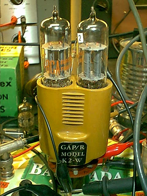
V1=12BZ7 V2=12BZ7
V1=12AX7 V2=12BZ7 and 47k resistor from Cathode of second stage at pin8 of V2, to ground. This reduces the excessive positive feedback evident in the previous plot, to get a flatter transfer curve in the following plot.
The 12AZ7 is designed to operate at several mA with mu=50 and gm=20mS, but it runs with less than one mA when plugged into the K2-W. At these low currents, the mu is down around 25 and gm is around 1mS. This cut down on the Avol of the K2-W. This tube might work if rebiased to run at higher currents.
The 12AV7 with mu=20 and gm=1mS with 150V at the plate and 0.6mA only works when plugged-in as V2 at the output, and it is a great misfit, as can be seen by the very low open loop gain of the K2-W.
The effect on step response:
Original V1=12AX7 V2=12AX7

The extra transconductance of the 12BZ7 appears to give a little overshoot, even with a gain of -20.
V1=12BZ7 V2=12BZ7

-------------------------- January 1, 2006:
Michel Vanden Broeck from Montereal has suggested several similar tube types that would improve output drive capacity of the K2-W. These types have a lower-mu/higher-power triode in the follower location of V2. The types are:
6FD7
6DR7
6CY7
7247/12DW7
I hope to find some of these tube types and try them out.